
|
|
||
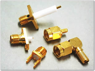
| SMA Connectors |
 |
| Features & Benefits |
| Applications | ||
| 50 Ω SMA Specifications | |
| Electrical | |
| Impedance | 50 O nominal |
| Frequency Range | .141" & .085" semi-rigid cable: 0-18 GHz Flexible cables: 0-12.4 GHz |
| Voltage Rating | RG-58, 141, 142: 500 volts peak RG-174, 188, 316: 375 volts peak |
| Dielectric Withstanding Voltage | .141" & RG-58 Cables: 1,000 VRMS .085" & RG-316 Cables: 750 VRMS |
| VSWR | Straight connector, .141": 1.05 + .005 f (GHz) |
| Contact Resistance | Center contact: 2.0 mΩ Body: 2.0 mΩ Braid to body: 0.5 mΩ |
| Insulation Resistance | 5,000 mΩ |
| RF Leakage | -90 dB minimum @ 2.3 GHz |
| Insertion Loss | dB maximum = .06v[f(GHz)] Test frequency @ 6.0 GHZ |
| Mechanical | |
| Mating | .250-36 threaded coupling |
| Mating Torque | Minimum: 2 inch pounds (12 N.cm) Recommended: 7-10 inch pounds (80-110 N.cm) Maximum: 15 inch pounds (170 N.cm) |
| Connector Durability | 100 matings |
| Material | |
| Bodies, Coupling Nuts, Other Metal Parts (except as noted) | Brass per QQ-B-626 |
| Contacts | Male: Brass Female: Beryllium copper, heat treated |
| Center Contact Plating | .000030" minimum gold |
| Plating (Other Metal Parts) | Standard .000010" gold or nickel plated |
| Insulator | TFE fluorocarbon |
| Male Center Contacts | Crimps: 20 - 100 lbsClamps: 20 - 50 lbs |
| Female Center Contact | Beryllium copper or phosphorous bronze, silver or gold plated |
| Other Metal Parts | Brass with nickel finish (except for M39012 which are silver) |
| Insulators | TFE fluorocarbon |
| Gaskets | Silicone rubber |
| Crimp Ferrule | Seamless copper tubing alloy |
| Environmental | |
| Temperature Range | -65°C to +165°C |
| Weatherproof | Crimp type: heat shrink tubing Solder type: silicone rubber gaskets |
| Thermal Shock | MIL-STD-202 method 107 (test condition B) except high temperatures @ + 200°C |
| Shock | MIL-STD-202 method 213 (test condition I). No discontinuity permitted. |
| Vibration | MIL-STD-202 method 204 (test condition D) |
| Corrosion | MIL-STD-202 method 101 (test condition B) 5% salt solution |
| Temperature Cycling | MIL-STD-202, method 102, test condition D |
| Altitude | MIL-STD-202 method 105 (test condition C), no corona at 70,000 feet. .141" & RG-55: 250 VRMS .085" & RG-122: 190 VRMS |
| Military | |
| MIL-C-39012 & MIL-C-83517 SMA Specification Sheets | Where applicable |
Note: These characteristics are typical but may not apply to all connectors.