
|
|
|||
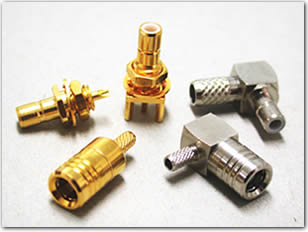
| SMB Connectors |
 |
| Features & Benefits |
| Applications | |||
| 50 Ω SMB Specifications | |
| Electrical | |
| Impedance | 50 Ω |
| Frequency Range | 0-4 GHz with low reflection; usable to 10.0 GHz |
| Voltage Rating | 335 volts at sea level and 85 volts at 70,000 feet |
| Dielectric Withstanding Voltage | RG-196: 750 VRMS; RG-188: 1,000 VRMS |
| VSWR | Straight connector, RG-196/U: 1.30 + .04 f (GHz) Right angle connector, RG-196/U: 1.45 + .06 f (GHz) Straight connector, RG-188/U: 1.25 + .04 f (GHz) Right angle connector, RG-188/U: 1.35 + .04 f (GHz) |
| Contact Resistance | Center contact: 6.0 mΩ initial, 8.0 after environmental; Outer contact: 1.0 mΩ initial, 1.5 after environmental Braid to body: 1.0 mΩ initial, after environmental N/A |
| MIL-C-39012 Insulation Resistance | 1,000 MΩ minimum |
| MIL-C-39012 RF Leakage | -55 dB minimum @ 2-3 GHz |
| MIL-C-39012 Insertion Loss | Straight connector: 0.30 dB @ 1.5 GHz Right angle connector: 0.60 dB @ 1.5 GHz |
| Mechanical | |
| Mating | Snap-on coupling per MIL-STD-348 |
| Braid/Jacket Cable Affixment | Hex crimp |
| Center Conductor Cable Affixment | Solder |
| Captivated Contacts | All crimps unless specified otherwise |
| Cable Retention | Equal to breaking strength of cable employed |
| Engagement Forces | Engagement: 14 lbs maximum Disengagement: 2 lbs minimum After 500 matings, 14 lbs maximum engagement and disengagement |
| Connector Durability | 500 mating cycles minimum |
| Material | |
| Center Contact | Female: beryllium copper, gold-plated Male: brass or beryllium copper, gold-plated |
| Outer Contact Plating | Nickel or gold plating as indicated |
| Body | Brass per QQB-626, or zinc per ASTM B86-71 |
| Body Plating | Nickel or gold plating as indicated |
| Insulator | TFE |
| Crimp Ferrule | Annealed copper alloy |
| Environmental | |
| Temperature Range | TFE insulators: - 65°C to + 165 °C, Copolymer of Styrene: - 55°C to + 85°C |
| Thermal Shock | MIL-STD-202 method 107, test condition B (except high temperatures @ 200°C |
| Shock | MIL-STD-202 method 202, method 13, snap-on, test condition B; 75 G's @ 6 milliseconds ½ sine |
| Vibration | MIL-STD-202 method 204, snap-on, test condition B; (15 G's) |
| Moisture | Resistance MIL-STD-202 method 106 |
| Corrosion | MIL-STD-202 method 101, test condition B. 5% salt solution |
Note: These characteristics are typical but may not apply to all connectors.