
|
|
|||
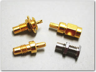
| SMC Connectors |
 |
| Features & Benefits |
| Applications | |||
| Type SMC Specifications | |
| Electrical | |
| Impedance | 50 O nominal |
| Frequency Range | 0-4 GHZ with low reflection; usable to 10.0 GHz |
| Voltage Rating | Sea level: 335 volts 70,000 ft: 85 volts |
| Dielectric Withstanding Voltage | 750 VRMS RG-196 1000 VRMS for RG-188 type |
| VSWR | RG-196/U series |
| Contact Resistance | Center contact: Outer contact: |
| Insulation Resistance | 1,000 MΩ minimum |
| RF Leakage | -55 dB minimum @ 2-3 GHz |
| Insertion Loss | Straight connectors: 0.30 dB @ 1.5 GHz Right angle connectors: 0.60 dB @ 1.5 GHz |
| Mechanical | |
| Mating | 50 Ohm screw-on coupling per MIL-STD-348 |
| Braid or Jacket Cable Affixment | Braid and Jacket: hex. crimp |
| Mating Torque | Recommended: 2-3" lbs. Maximum: 6.6" lbs. 80-110 N.cm |
| Center Conductor Cable Affixment | Solder |
| Connector Durability | 500 mating and unmating cycles min. |
| Material | |
| Body | Brass per QQB-626 or zinc per ASTM B86-71, as specified, nickel or gold plated as listed |
| Male Contacts | Male: brass or beryllium copper, gold plated |
| Female Contacts | Female: beryllium copper, gold plated. |
| Insulators | TFE |
| Outer Contact | Nickel or gold plated as listed |
| Crimp Ferrule | Annealed copper alloys |
| Environmental | |
| Temperature Range | TFE: -65°C to +165°C |
| Thermal Shock | MIL-STD-202 method 107 condition C |
| Vibration | MIL-STD-202 method 204 condition D |
| Vibration | MIL-STD-202, method 204, test condition B |
| Corrosion | MIL-STD-202 method 101 condition B |
| Shock | MIL-STD-202 method 213 condition C |
Note: These characteristics are typical but may not apply to all connectors.